Pulse Width Modulation (PWM)


Pulse-width modulation (PWM), or pulse-duration modulation (PDM), is a method of controlling the average power delivered by an electrical signal.


Fig: An example of PWM in an idealized inductor driven by a blue line voltage source modulated as a series of sawtooth pulses, resulting in a red line current in the inductor. 


Generating a PWM Signal

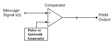
The simplest way to generate a PWM signal is the intersection method, which requires only a sawtooth or a triangle waveform (easily generated using a simple oscillator) and a comparator. When the value of the reference signal is more than the modulation waveform, the PWM signal (magenta) is in the high state; otherwise, it is in the low state. 


Duty cycle

A low duty cycle equates to low power because the power is off for most of the time; the word duty cycle reflects the ratio of "on" time to the regular interval or "period" of time. The duty cycle is measured in percent, with 100% representing full on. A digital signal has a duty cycle of 50% and looks like a "square" wave when it is on 50% of the time and off the other 50%. A digital signal has a duty cycle of greater than 50% when it spends more time in the on state than the off state. A digital signal has a duty cycle of 50% when it alternates between the on and off states more often than not.


Mathematical Formulation of pulse-width waveform

Pulse-width modulation uses a rectangular pulse wave whose pulse width is modulated resulting in the variation of the average value of the waveform. If we consider a pulse waveform f(t), with period T, low-value ymin, a high-value ymax, and a duty cycle D, the average value of the waveform is given by


Average Value of the Signal and PWM Generation

The average value of the signal is given by:

\[ \bar{y} = \frac{1}{T} \int_0^T f(t) \, dt \] As \(f(t)\) is a pulse wave, its value is \(y_\text{max}\) for \(0 < t < D \cdot T\) and \(y_\text{min}\) for \(D \cdot T < t < T\). The above expression then becomes:

\[ \bar{y} = \frac{1}{T} \int_0^{D \cdot T} y_\text{max} \, dt + \frac{1}{T} \int_{D \cdot T}^T y_\text{min} \, dt \] \[ = \frac{1}{T} \left(D \cdot T \cdot y_\text{max} + T(1 - D) \cdot y_\text{min}\right) \] \[ = D \cdot y_\text{max} + (1 - D) \cdot y_\text{min} \]

From this, the average value of the signal (\(\bar{y}\)) is directly dependent on the duty cycle \(D\). 


Further Reading

People are good at skipping over material they already know!

View Related Topics to


Contact Us

Name

Email *

Message *

Popular Posts

BER vs SNR for M-ary QAM, M-ary PSK, QPSK, BPSK, ...

📘 Overview of BER and SNR 🧮 Online Simulator for BER calculation of m-ary QAM and m-ary PSK 🧮 MATLAB Code for BER calculation of M-ary QAM, M-ary PSK, QPSK, BPSK, ... 📚 Further Reading 📂 View Other Topics on M-ary QAM, M-ary PSK, QPSK ... 🧮 Online Simulator for Constellation Diagram of m-ary QAM 🧮 Online Simulator for Constellation Diagram of m-ary PSK 🧮 MATLAB Code for BER calculation of ASK, FSK, and PSK 🧮 MATLAB Code for BER calculation of Alamouti Scheme 🧮 Different approaches to calculate BER vs SNR What is Bit Error Rate (BER)? The abbreviation BER stands for Bit Error Rate, which indicates how many corrupted bits are received (after the demodulation process) compared to the total number of bits sent in a communication process. BER = (number of bits received in error) / (total number of tran...

Online Simulator for ASK, FSK, and PSK

Try our new Digital Signal Processing Simulator!   Start Simulator for binary ASK Modulation Message Bits (e.g. 1,0,1,0) Carrier Frequency (Hz) Sampling Frequency (Hz) Run Simulation Simulator for binary FSK Modulation Input Bits (e.g. 1,0,1,0) Freq for '1' (Hz) Freq for '0' (Hz) Sampling Rate (Hz) Visualize FSK Signal Simulator for BPSK Modulation ...

OFDM Symbols and Subcarriers Explained

This article explains how OFDM (Orthogonal Frequency Division Multiplexing) symbols and subcarriers work. It covers modulation, mapping symbols to subcarriers, subcarrier frequency spacing, IFFT synthesis, cyclic prefix, and transmission. Step 1: Modulation First, modulate the input bitstream. For example, with 16-QAM , each group of 4 bits maps to one QAM symbol. Suppose we generate a sequence of QAM symbols: s0, s1, s2, s3, s4, s5, …, s63 Step 2: Mapping Symbols to Subcarriers Assume N sub = 8 subcarriers. Each OFDM symbol in the frequency domain contains 8 QAM symbols (one per subcarrier): Mapping (example) OFDM symbol 1 → s0, s1, s2, s3, s4, s5, s6, s7 OFDM symbol 2 → s8, s9, s10, s11, s12, s13, s14, s15 … OFDM sym...

Constellation Diagrams of ASK, PSK, and FSK

📘 Overview of Energy per Bit (Eb / N0) 🧮 Online Simulator for constellation diagrams of ASK, FSK, and PSK 🧮 Theory behind Constellation Diagrams of ASK, FSK, and PSK 🧮 MATLAB Codes for Constellation Diagrams of ASK, FSK, and PSK 📚 Further Reading 📂 Other Topics on Constellation Diagrams of ASK, PSK, and FSK ... 🧮 Simulator for constellation diagrams of m-ary PSK 🧮 Simulator for constellation diagrams of m-ary QAM BASK (Binary ASK) Modulation: Transmits one of two signals: 0 or -√Eb, where Eb​ is the energy per bit. These signals represent binary 0 and 1.    BFSK (Binary FSK) Modulation: Transmits one of two signals: +√Eb​ ( On the y-axis, the phase shift of 90 degrees with respect to the x-axis, which is also termed phase offset ) or √Eb (on x-axis), where Eb​ is the energy per bit. These signals represent binary 0 and 1.  BPSK (Binary PSK) Modulation: Transmits one of two signals...

Bartlett Method in MATLAB

Steps to calculate Spectral power density using Bartlett Method 'M' is the length of each segment for the Bartlett method, set to 100 samples. 'K' is the number of segments obtained by dividing the total number of samples N by the segment length 'M'. psd_bartlett_broadband is initialized to store the accumulated periodogram. For each segment k, x_k extracts the k-th segment of the broadband signal. P_k computes the periodogram of the k-th segment using the FFT. The periodograms are accumulated and averaged over all segments. The PSD is plotted in dB/Hz by converting the power values to decibels using 10 * log10.   MATLAB Script clc; clear; close all; % Parameters fs = 1000; % Sampling frequency t = 0:1/fs:1-1/fs; % Time vector N = length(t); % Number of samples % Generate synthetic broadband ARMA process arma_order = [2, 2]; % ARMA(p,q) order a = [1, -0.75, 0....

Comparisons among ASK, PSK, and FSK | And the definitions of each

📘 Comparisons among ASK, FSK, and PSK 🧮 Online Simulator for calculating Bandwidth of ASK, FSK, and PSK 🧮 MATLAB Code for BER vs. SNR Analysis of ASK, FSK, and PSK 📚 Further Reading 📂 View Other Topics on Comparisons among ASK, PSK, and FSK ... 🧮 Comparisons of Noise Sensitivity, Bandwidth, Complexity, etc. 🧮 MATLAB Code for Constellation Diagrams of ASK, FSK, and PSK 🧮 Online Simulator for ASK, FSK, and PSK Generation 🧮 Online Simulator for ASK, FSK, and PSK Constellation 🧮 Some Questions and Answers Modulation ASK, FSK & PSK Constellation MATLAB Simulink MATLAB Code Comparisons among ASK, PSK, and FSK    Comparisons among ASK, PSK, and FSK Comparison among ASK, FSK, and PSK Parameters ASK FSK PSK Variable Characteristics Amplitude Frequency ...

UGC NET Electronic Science Previous Year Question Papers

Home / Engineering & Other Exams / UGC NET 2022: Previous Year Question Papers ... UGC-NET (Electronics Science, Subject code: 88) UGC Net Electronic Science Question Paper With Answer Key Download Pdf [December 2024] UGC Net Electronic Science Question Paper With Answer Key Download Pdf [June 2024] UGC Net Electronic Science Question Paper With Answer Key Download Pdf [December 2023] UGC Net Electronic Science Question Paper With Answer Key Download Pdf [June 2023] UGC Net Electronic Science Question Paper With Answer Key Download Pdf [December 2022] UGC Net Electronic Science Question Paper With Answer Key Download Pdf [June 2022] UGC Net Electronic Science Question Paper With Answer Key Download Pdf [December 2021] UGC Net Electronic Science Question With Answer Key Download Pdf [June 2020] UGC Net Electronic Science Question With Answer Key Download Pdf [December 2019] UGC Net Elec...

OFDM for 4G & 5G

📘 Overview 📘 Example: (OFDM using QPSK) 🧮 MATLAB Codes 🧮 Q & A and Summary 📚 Further Reading   Orthogonal Frequency Division Multiplexing When a signal with high bandwidth traverses through a medium, it tends to disperse more compared to a signal with lower bandwidth. A high-bandwidth signal comprises a wide range of frequency components. Each frequency component may interact differently with the transmission medium due to factors such as attenuation, dispersion, and distortion. OFDM combats the high-bandwidth frequency selective channel by dividing the original signal into multiple orthogonal multiplexed narrowband signals. In this way it, overcomes the inter-symbol interferences (ISI) issue. Block Diagram     ‘k’ indicates kth position in a input symbol N is the number of subcarriers   Example: (OFDM using QPSK) 1.        Input Parameters: N   Number of Input bits: 128 Number ...