
Antenna array response


Antenna array response

In case of wireless communication signal reaches receiver thru multipath. Multipath signals are correlated if antenna elements are closely packed in a compact region.

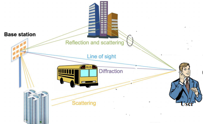
Figure 1: Illustration of multipath communication in wireless environment

For a path l (say) is described along following parameters

  1. Angle of arrival θrl ;

  2. Angle of departure θtl ;

  3. Complex channel gain αl ;

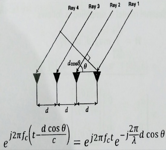
Figure 2: Directional cosine vectors at receiver side for transmission from Tx

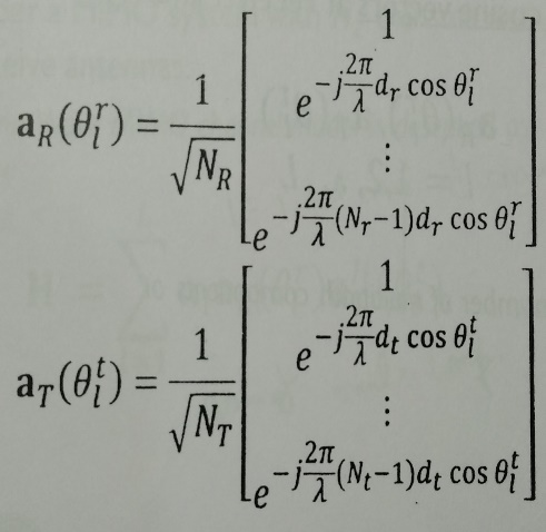
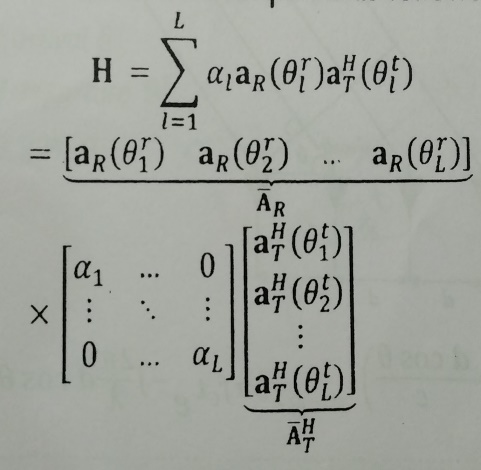
Figure 3: Antenna array response at different antenna array and simplified channel model

Let assume, in the above figure 2, BS is transmitting at receiver side and receiver antenna array contain four ULA antenna elements. Then we can observe in the figure that to reach 2nd element (from left) the signal has to travel more distance with compare to 1st element. The extra path distance will be dcosθ or λ/2*cosθ as the antenna elements are spaced in half wave length interval. That’s why there will be time difference for signal to reach in 2nd element is dcosθ/c or λ/2*cosθ/c; where, c = speed of EM wave and phases will be changed accordingly as shown in above figure.

In the above figure the extra phase difference will be exp(j*2*pi*fc*d*cosθ/c) which is equal to exp(j*2*pi* dcosθ/ λ) or simply, exp(j*pi* cosθ) as d=λ/2.

So, the antenna array response for ULA will be
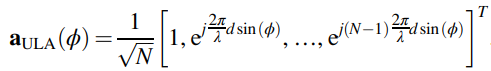
……………..(i)

Similarly, for URA (W1 & W2 elements on the x and y axes) antenna response will be

……………....(ii)

(El Ayach, 2014)

Here the extra term sinφ and ycosθ come for rectangular geometry of the antenna array


People are good at skipping over material they already know!

View Related Topics to


Contact Us

Name

Email *

Message *

Popular Posts

BER vs SNR for M-ary QAM, M-ary PSK, QPSK, BPSK, ...(MATLAB Code + Simulator)

📘 Overview of BER and SNR 🧮 Online Simulator for BER calculation 🧮 MATLAB Code for BER calculation 📚 Further Reading 📂 View Other Topics on M-ary QAM, M-ary PSK, QPSK ... 🧮 Online Simulator for Constellation Diagram of m-ary QAM 🧮 Online Simulator for Constellation Diagram of m-ary PSK 🧮 MATLAB Code for BER calculation of ASK, FSK, and PSK 🧮 MATLAB Code for BER calculation of Alamouti Scheme 🧮 Different approaches to calculate BER vs SNR What is Bit Error Rate (BER)? The abbreviation BER stands for Bit Error Rate, which indicates how many corrupted bits are received compared to the total number of bits sent. BER = (number of bits received in error) / (total number of transmitted bits) What is Signal-to-Noise Ratio (SNR)? SNR is the ratio of signal power to noise powe...

ASK, FSK, and PSK (with MATLAB + Online Simulator)

📘 Overview 📘 Amplitude Shift Keying (ASK) 📘 Frequency Shift Keying (FSK) 📘 Phase Shift Keying (PSK) 📘 Which of the modulation techniques—ASK, FSK, or PSK—can achieve higher bit rates? 🧮 MATLAB Codes 📘 Simulator for binary ASK, FSK, and PSK Modulation 📚 Further Reading ASK or OFF ON Keying ASK is a simple (less complex) Digital Modulation Scheme where we vary the modulation signal's amplitude or voltage by the message signal's amplitude or voltage. We select two levels (two different voltage levels) for transmitting modulated message signals. For example, "+5 Volt" (upper level) and "0 Volt" (lower level). To transmit binary bit "1", the transmitter sends "+5 Volts", and for bit "0", it sends no power. The receiver uses filters to detect whether a binary "1" or "0" was transmitted. ...

Calculation of SNR from FFT bins in MATLAB

📘 Overview 🧮 MATLAB Code for Estimation of SNR from FFT bins 🧮 MATLAB Code for SNR from PSD using Kaiser Window 📚 Further Reading Here, you can find the SNR of a received signal from periodogram / FFT bins using the Kaiser operator. The beta (β) parameter characterizes the Kaiser window, which controls the trade-off between the main lobe width and the side lobe level. Steps Set up the sampling rate and time vector Compute the FFT and periodogram Calculate the frequency resolution and signal power Exclude the signal power from noise calculation Compute the noise power and SNR MATLAB Code for Estimation of SNR from FFT bins clc; clear; close all; % Parameters fs = 8000; f_tone = 1000; N = 8192; t = (0:N-1)/fs; % Generate signal + noise signal = sin(2*pi*f_tone*t); SNR_true_dB = 20; signal_power = mean(signal.^2); noise_power = signal_power / (10^(SNR_true_dB/10)); noisy_signal = signal + sqrt(noise_power) * randn(1, N); % Apply ...

Online Simulator for ASK, FSK, and PSK

Try our new Digital Signal Processing Simulator!   Start Simulator for binary ASK Modulation Message Bits (e.g. 1,0,1,0) Carrier Frequency (Hz) Sampling Frequency (Hz) Run Simulation Simulator for binary FSK Modulation Input Bits (e.g. 1,0,1,0) Freq for '1' (Hz) Freq for '0' (Hz) Sampling Rate (Hz) Visualize FSK Signal Simulator for BPSK Modulation ...

MATLAB Code for ASK, FSK, and PSK (with Online Simulator)

📘 Overview & Theory 🧮 MATLAB Code for ASK 🧮 MATLAB Code for FSK 🧮 MATLAB Code for PSK 🧮 Simulator for binary ASK, FSK, and PSK Modulations 📚 Further Reading ASK, FSK & PSK HomePage MATLAB Code MATLAB Code for ASK Modulation and Demodulation % The code is written by SalimWireless.Com % Clear previous data and plots clc; clear all; close all; % Parameters Tb = 1; % Bit duration (s) fc = 10; % Carrier frequency (Hz) N_bits = 10; % Number of bits Fs = 100 * fc; % Sampling frequency (ensure at least 2*fc, more for better representation) Ts = 1/Fs; % Sampling interval samples_per_bit = Fs * Tb; % Number of samples per bit duration % Generate random binary data rng(10); % Set random seed for reproducibility binary_data = randi([0, 1], 1, N_bits); % Generate random binary data (0 or 1) % Initialize arrays for continuous signals t_overall = 0:Ts:(N_bits...

Comparing Baseband and Passband Implementations of ASK, FSK, and PSK

📘 Overview 🧮 Baseband and Passband Implementations of ASK, FSK, and PSK 🧮 Difference betwen baseband and passband 📚 Further Reading 📂 Other Topics on Baseband and Passband ... 🧮 Baseband modulation techniques 🧮 Passband modulation techniques   Baseband modulation techniques are methods used to encode information signals onto a baseband signal (a signal with frequencies close to zero). Passband techniques shift these signals to higher carrier frequencies for transmission. Here are the common implementations: Amplitude Shift Keying (ASK) [↗] : In ASK, the amplitude of the signal is varied to represent different symbols. Binary ASK (BASK) is a common implementation where two different amplitudes represent binary values (0 and 1). ASK is simple but susceptible to noise. ASK Baseband (Digital Bits) ASK Passband (Modulated Carrier)     Fig 1:  ASK Passband Modulation (...

Comparing Baseband and Passband Implementations of m-ary QAM

  Let's assume your original digital message bitstream is: 0, 0, 1, 0, 0, 0, 1, 0, 1, 1 In 4-QAM, we group them into pairs: (00), (10), (00), (10), (11). Your baseband symbols are: Symbol 1 (Bits 00): -1.00 - j1.00 Symbol 2 (Bits 10): 1.00 - j1.00 Symbol 3 (Bits 00): -1.00 - j1.00 Symbol 4 (Bits 10): 1.00 - j1.00 Symbol 5 (Bits 11): 1.00 + j1.00   To transmit these symbols over a wireless medium, we modulate this baseband signal onto a high-frequency carrier (e.g., 50 Hz). This process creates the passband signal , where the information is stored in the phase and amplitude of the sine wave. Fig 1: 4-QAM Baseband I and Q Components Fig 2: 4-QAM Passband Modulated Signal   In this example, the symbol rate is 5 symbols per second. Detailed Explanation 4-QAM Constellation Mapping In standard 4-QAM mapping, bits are converted to complex points on a grid: Bits...

Constellation Diagrams of ASK, PSK, and FSK with MATLAB Code + Simulator

📘 Overview of Energy per Bit (Eb / N0) 🧮 Online Simulator for constellation diagrams of ASK, FSK, and PSK 🧮 Theory behind Constellation Diagrams of ASK, FSK, and PSK 🧮 MATLAB Codes for Constellation Diagrams of ASK, FSK, and PSK 📚 Further Reading 📂 Other Topics on Constellation Diagrams of ASK, PSK, and FSK ... 🧮 Simulator for constellation diagrams of m-ary PSK 🧮 Simulator for constellation diagrams of m-ary QAM BASK (Binary ASK) Modulation: Transmits one of two signals: 0 or -√Eb, where Eb​ is the energy per bit. These signals represent binary 0 and 1.    BFSK (Binary FSK) Modulation: Transmits one of two signals: +√Eb​ ( On the y-axis, the phase shift of 90 degrees with respect to the x-axis, which is also termed phase offset ) or √Eb (on x-axis), where Eb​ is the energy per bit. These signals represent binary 0 and 1.  BPSK (Binary PSK) Modulation: Transmits one of two signals...