Design of CMOS XOR/XNOR Gates


Design of CMOS XOR/XNOR Gates

The semiconductor industry has experienced rapid integration of multimedia applications into mobile electronics, leading to very high integration density in CMOS VLSI. As operating frequencies increase, power consumption, speed, silicon area, and reliability become critical considerations.

The XOR-XNOR circuits are fundamental building blocks in arithmetic circuits (Full Adders, Multipliers), compressors, comparators, parity checkers, code converters, error-detecting/correcting codes, and phase detectors. Their performance directly impacts the complex circuits they are used in. Design goals include full output voltage swing, low power consumption, reduced transistor count, minimal delay, and simultaneous non-skewed outputs.

Static Logic (Static CMOS)

Static CMOS gates always provide a mechanism to drive outputs high or low.

  • Pull-Up Network (PUN): Connects output to VDD when output = 1.
  • Pull-Down Network (PDN): Connects output to VSS when output = 0.

The PUN and PDN are mutually exclusive; only one conducts at a time.
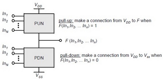
Complementary logic gate showing pull-up and pull-down networks
Fig.1: Complementary logic gate using PUN & PDN

Dynamic Logic

Dynamic logic uses a clock signal for combinational logic. It requires a minimum clock rate to ensure outputs are used before leakage. The PDN is similar to static CMOS. Operation occurs in two phases:

  • Pre-charge (CLK=0): The output is charged to VDD via the PMOS transistor; the PDN is off.
  • Evaluation (CLK=1): The PMOS pre-charge transistor turns off, the NMOS evaluation transistor turns on. The output discharges conditionally based on inputs.
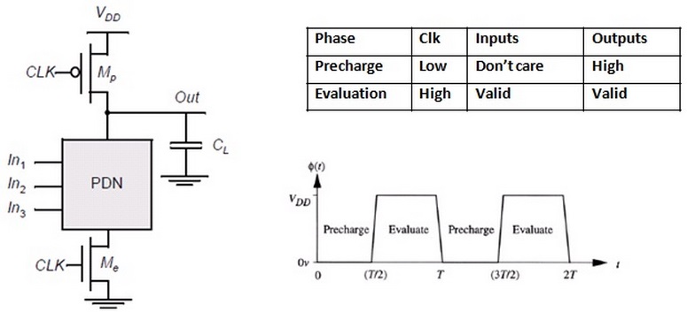
Dynamic logic gate operation showing pre-charge and evaluation phases
Fig.2: Dynamic gate operation (Pre-charge/Evaluation)

CMOS XOR & XNOR Gates

Static CMOS XOR/XNOR circuits use complementary PUN and PDN networks. They provide full output swing but require more transistors.

Logic expressions:

Z = A ⊕ B = (A + B)(A′ + B′)
Z′ = (A ⊕ B)′ = AB + A′B′
Z = (AB + A′B′)′ = A ⊕ B

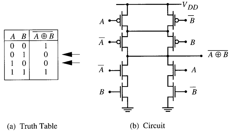
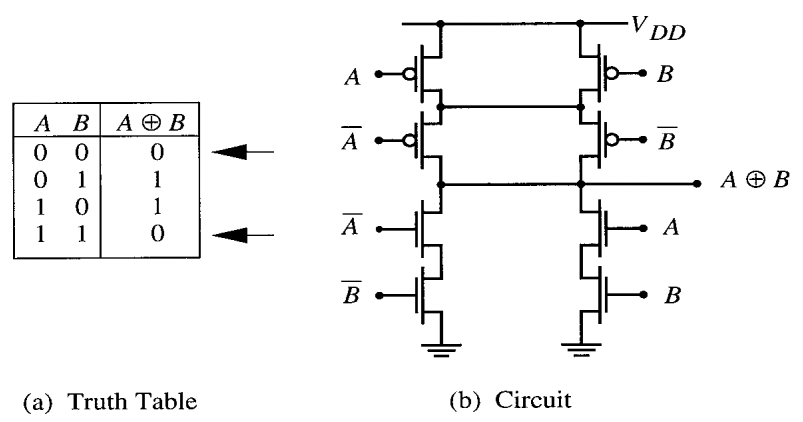
Alternative realization of XOR/XNOR using CMOS is shown below:
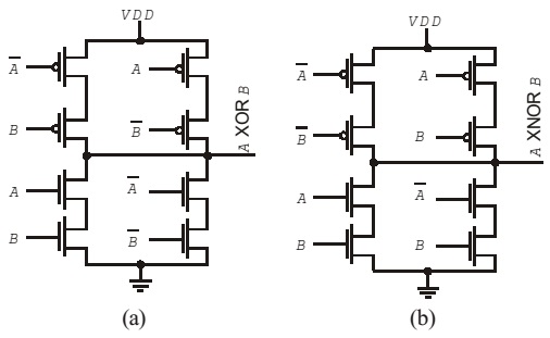
Basic CMOS implementation of XOR and XNOR gates
Fig.3: XOR (a) & XNOR (b) gates using CMOS
Combined CMOS circuit implementing XOR and XNOR
Fig.4: Implementation of XOR & XNOR in one circuit
XNOR circuit diagram along with truth table
Fig.5: XNOR Circuit & Truth Table
XOR circuit diagram along with truth table
Fig.6: XOR Circuit & Truth Table

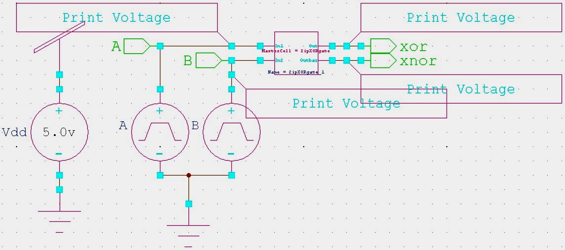
Circuit Simulation / Block Diagram

Transient response simulation of XOR XNOR circuit in S-Edit
Fig.7: XOR/XNOR Circuit using S-Edit (Transient Response)
Master cell design of XOR XNOR circuit using S-Edit
Fig.8: Master Cell XOR/XNOR using S-Edit

Programming (SPICE Command)

SPICE code is extracted using T-Edit.

Graphs (W-Edit)

Simulate the schematic and generate waveforms corresponding to inputs using W-Edit.

Conclusions

In this experiment, the transient response of CMOS XOR/XNOR gates was studied. Waveforms were obtained using W-Edit, and SPICE code was extracted using T-Edit. The experiment demonstrates the design and analysis of XOR/XNOR gates in CMOS technology.


Contact Us

Name

Email *

Message *

Popular Posts

UGC NET Electronic Science Previous Year Question Papers with Solutions

Download Papers and Solutions Exam Pattern Preparation Tips FAQs More Home / Engineering & Other Exams / UGC NET 2026 PYQ 📊 Exam Highlights: Electronic Science (88) Feature Details Junior Research Fellowship (JRF) ₹37,000 + HRA per month Eligibility M.Sc/M.Tech in Electronics (55%) Validity of Certificate JRF (3 Years) | Lectureship (Lifetime) 📥 Download UGC NET Electronics PDFs Complete collection of previous year question papers, answer keys and explanations for Subject Code 88. Start Downloading 📂 View All Question Papers June 2026 - Question Paper Download PDF June 202...

Online Simulator for ASK, FSK, and PSK Signal Generation

Interactive Digital Signal Processing (DSP) Tutorial and Simulator for ASK, FSK, and BPSK modulation techniques. Try our new Digital Signal Processing Simulator!   •   Interactive ASK, FSK, and BPSK tools updated for 2025. Start Now Digital Modulation Visualizer: ASK, FSK, & BPSK Simulator Learn and visualize binary modulation techniques (ASK, FSK, BPSK) in real-time with adjustable carrier and sampling parameters. Perfect for DSP students and engineers. 📡 ASK Simulator 📶 FSK Simulator 🎚️ BPSK Simulator 📚 More Topics ASK Modulator FSK Modulator BPSK Modulator Demodulation More Topics 1. ASK (Ampli...

Linear vs Circular Convolution

Linear vs Circular Convolution Linear convolution vs circular convolution Linear convolution (what nature does) If: x[n] = transmitted signal h[n] = channel impulse response (multipath) Then the received signal is: y[n] = x[n] * h[n] This means: Past symbols spill into future symbols Causes inter-symbol interference (ISI) DFT of y[n] is not a simple product Circular convolution (what DFT assumes) The DFT assumes periodic signals : y[n] = x[n] ⊛ h[n], where indices wrap around modulo N Only under circular convolution does the DFT satisfy: Y[k] = X[k] · H[k] This is what enables one-tap frequency-domain equalization . What happens in the real channel (linear convolution) The channel performs linear convolution: y[n] = Σ l=0 Lh−1 h[l] x[n-l] But because: CP absorbs the “spillover” Receiver discards CP before DFT The useful part of the received symbol becomes: y[n] = Σ l=0 Lh−1 h[l] x[(n-l) mod N] Modulo inde...

Flat vs Frequency Selective Online Simulator

Flat vs Frequency Selective Online Simulator Channel Type Without Fading Flat Fading Multipaths Nakagami m SNR(dB) Run Simulation Input Signal Signal After Fading Constellation Diagram BER vs SNR Explore Advanced Flat vs Frequency-Selective Fading Simulator Want to see these equations in action? Visualize it. Launch Simulator Tool Interactive Rayleigh Fading Simulator Want to see Rayleigh fading in action? Visualize it. Launch Simulator Tool Return to DSP Simulations Main Page →

Theoretical BER vs SNR for binary ASK, FSK, and PSK (with MATLAB Code + Simulator)

📘 Overview & Theory 🧮 MATLAB Codes 🧮 Q-function 📚 Further Reading Bit Error Rate (BER) Equations In ASK, noise directly affects the signal amplitude, making it the most vulnerable since the data is carried in amplitude changes. In FSK, data is represented by frequency variations, and because noise typically impacts amplitude more than frequency, FSK is more robust than ASK. In PSK, data is encoded in the signal phase, and BPSK specifically uses 180-degree phase shifts, creating the greatest separation between signal points and therefore achieving the lowest bit error rate (BER) for the same power level. BER formulas for ASK, FSK, and PSK modulation schemes. ASK BER = 0.5 × erfc(0.5 × √SNR) FSK BER = 0.5 × erfc(√(SNR / 2)) PSK BER = 0.5 × erfc(√SNR) ...

Constellation Diagrams of ASK, PSK, and FSK (with MATLAB Code + Simulator)

Constellation Diagrams: ASK, FSK, and PSK Comprehensive guide to signal space representation, including interactive simulators and MATLAB implementations. 📘 Overview 🧮 Simulator ⚖️ Theory 📈 Q-function 📚 Resources BASK Modulation Transmits one of two signals: 0 or $\sqrt{E_b}$, representing binary 0 and 1. Simple but sensitive to noise. BFSK Modulation Transmits one of two signals: $\sqrt{E_b}$ on the Y-axis or $\sqrt{E_b}$ on the X-axis. These are orthogonal signals. BPSK Modulation Transmits $+\sqrt{E_b}$ or $-\sqrt{E_b}$ (antipodal signaling). Most efficient binary scheme. ...