
Design of CMOS XOR/XNOR Gates


Design of CMOS XOR/XNOR Gates

The semiconductor industry has experienced rapid integration of multimedia applications into mobile electronics, leading to very high integration density in CMOS VLSI. As operating frequencies increase, power consumption, speed, silicon area, and reliability become critical considerations.

The XOR-XNOR circuits are fundamental building blocks in arithmetic circuits (Full Adders, Multipliers), compressors, comparators, parity checkers, code converters, error-detecting/correcting codes, and phase detectors. Their performance directly impacts the complex circuits they are used in. Design goals include full output voltage swing, low power consumption, reduced transistor count, minimal delay, and simultaneous non-skewed outputs.

Static Logic (Static CMOS)

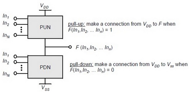
Static CMOS gates always provide a mechanism to drive outputs high or low.

  • Pull-Up Network (PUN): Connects output to VDD when output = 1.
  • Pull-Down Network (PDN): Connects output to VSS when output = 0.

The PUN and PDN are mutually exclusive; only one conducts at a time.

Complementary logic gate showing pull-up and pull-down networks
Fig.1: Complementary logic gate using PUN & PDN

Dynamic Logic

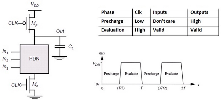
Dynamic logic uses a clock signal for combinational logic. It requires a minimum clock rate to ensure outputs are used before leakage. The PDN is similar to static CMOS. Operation occurs in two phases:

  • Pre-charge (CLK=0): The output is charged to VDD via the PMOS transistor; the PDN is off.
  • Evaluation (CLK=1): The PMOS pre-charge transistor turns off, the NMOS evaluation transistor turns on. The output discharges conditionally based on inputs.
Dynamic logic gate operation showing pre-charge and evaluation phases
Fig.2: Dynamic gate operation (Pre-charge/Evaluation)

CMOS XOR & XNOR Gates

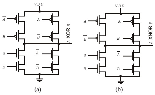
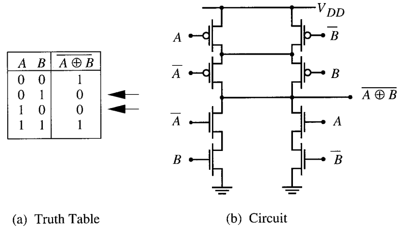
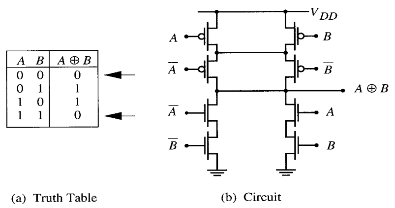
Static CMOS XOR/XNOR circuits use complementary PUN and PDN networks. They provide full output swing but require more transistors.

Logic expressions:

Z = A ⊕ B = (A + B)(A′ + B′)
Z′ = (A ⊕ B)′ = AB + A′B′
Z = (AB + A′B′)′ = A ⊕ B

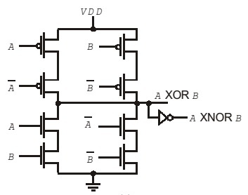
Alternative realization of XOR/XNOR using CMOS is shown below:

Basic CMOS implementation of XOR and XNOR gates
Fig.3: XOR (a) & XNOR (b) gates using CMOS
Combined CMOS circuit implementing XOR and XNOR
Fig.4: Implementation of XOR & XNOR in one circuit
XNOR circuit diagram along with truth table
Fig.5: XNOR Circuit & Truth Table
XOR circuit diagram along with truth table
Fig.6: XOR Circuit & Truth Table

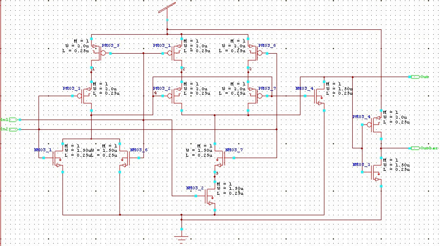
Circuit Simulation / Block Diagram

Transient response simulation of XOR XNOR circuit in S-Edit
Fig.7: XOR/XNOR Circuit using S-Edit (Transient Response)
Master cell design of XOR XNOR circuit using S-Edit
Fig.8: Master Cell XOR/XNOR using S-Edit

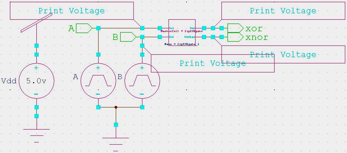
Programming (SPICE Command)

SPICE code is extracted using T-Edit.

Graphs (W-Edit)

Simulate the schematic and generate waveforms corresponding to inputs using W-Edit.

Conclusions

In this experiment, the transient response of CMOS XOR/XNOR gates was studied. Waveforms were obtained using W-Edit, and SPICE code was extracted using T-Edit. The experiment demonstrates the design and analysis of XOR/XNOR gates in CMOS technology.

People are good at skipping over material they already know!

View Related Topics to


Contact Us

Name

Email *

Message *

Popular Posts

BER vs SNR for M-ary QAM, M-ary PSK, QPSK, BPSK, ...(MATLAB Code + Simulator)

📘 Overview of BER and SNR 🧮 Online Simulator for BER calculation 🧮 MATLAB Code for BER calculation 📚 Further Reading 📂 View Other Topics on M-ary QAM, M-ary PSK, QPSK ... 🧮 Online Simulator for Constellation Diagram of m-ary QAM 🧮 Online Simulator for Constellation Diagram of m-ary PSK 🧮 MATLAB Code for BER calculation of ASK, FSK, and PSK 🧮 MATLAB Code for BER calculation of Alamouti Scheme 🧮 Different approaches to calculate BER vs SNR What is Bit Error Rate (BER)? The abbreviation BER stands for Bit Error Rate, which indicates how many corrupted bits are received compared to the total number of bits sent. BER = (number of bits received in error) / (total number of transmitted bits) What is Signal-to-Noise Ratio (SNR)? SNR is the ratio of signal power to noise powe...

ASK, FSK, and PSK (with MATLAB + Online Simulator)

📘 Overview 📘 Amplitude Shift Keying (ASK) 📘 Frequency Shift Keying (FSK) 📘 Phase Shift Keying (PSK) 📘 Which of the modulation techniques—ASK, FSK, or PSK—can achieve higher bit rates? 🧮 MATLAB Codes 📘 Simulator for binary ASK, FSK, and PSK Modulation 📚 Further Reading ASK or OFF ON Keying ASK is a simple (less complex) Digital Modulation Scheme where we vary the modulation signal's amplitude or voltage by the message signal's amplitude or voltage. We select two levels (two different voltage levels) for transmitting modulated message signals. For example, "+5 Volt" (upper level) and "0 Volt" (lower level). To transmit binary bit "1", the transmitter sends "+5 Volts", and for bit "0", it sends no power. The receiver uses filters to detect whether a binary "1" or "0" was transmitted. ...

Calculation of SNR from FFT bins in MATLAB

📘 Overview 🧮 MATLAB Code for Estimation of SNR from FFT bins 🧮 MATLAB Code for SNR from PSD using Kaiser Window 📚 Further Reading Here, you can find the SNR of a received signal from periodogram / FFT bins using the Kaiser operator. The beta (β) parameter characterizes the Kaiser window, which controls the trade-off between the main lobe width and the side lobe level. Steps Set up the sampling rate and time vector Compute the FFT and periodogram Calculate the frequency resolution and signal power Exclude the signal power from noise calculation Compute the noise power and SNR MATLAB Code for Estimation of SNR from FFT bins clc; clear; close all; % Parameters fs = 8000; f_tone = 1000; N = 8192; t = (0:N-1)/fs; % Generate signal + noise signal = sin(2*pi*f_tone*t); SNR_true_dB = 20; signal_power = mean(signal.^2); noise_power = signal_power / (10^(SNR_true_dB/10)); noisy_signal = signal + sqrt(noise_power) * randn(1, N); % Apply ...

Online Simulator for ASK, FSK, and PSK

Try our new Digital Signal Processing Simulator!   Start Simulator for binary ASK Modulation Message Bits (e.g. 1,0,1,0) Carrier Frequency (Hz) Sampling Frequency (Hz) Run Simulation Simulator for binary FSK Modulation Input Bits (e.g. 1,0,1,0) Freq for '1' (Hz) Freq for '0' (Hz) Sampling Rate (Hz) Visualize FSK Signal Simulator for BPSK Modulation ...

Comparing Baseband and Passband Implementations of ASK, FSK, and PSK

📘 Overview 🧮 Baseband and Passband Implementations of ASK, FSK, and PSK 🧮 Difference betwen baseband and passband 📚 Further Reading 📂 Other Topics on Baseband and Passband ... 🧮 Baseband modulation techniques 🧮 Passband modulation techniques   Baseband modulation techniques are methods used to encode information signals onto a baseband signal (a signal with frequencies close to zero). Passband techniques shift these signals to higher carrier frequencies for transmission. Here are the common implementations: Amplitude Shift Keying (ASK) [↗] : In ASK, the amplitude of the signal is varied to represent different symbols. Binary ASK (BASK) is a common implementation where two different amplitudes represent binary values (0 and 1). ASK is simple but susceptible to noise. ASK Baseband (Digital Bits) ASK Passband (Modulated Carrier)     Fig 1:  ASK Passband Modulation (...

Comparing Baseband and Passband Implementations of m-ary QAM

  Let's assume your original digital message bitstream is: 0, 0, 1, 0, 0, 0, 1, 0, 1, 1 In 4-QAM, we group them into pairs: (00), (10), (00), (10), (11). Your baseband symbols are: Symbol 1 (Bits 00): -1.00 - j1.00 Symbol 2 (Bits 10): 1.00 - j1.00 Symbol 3 (Bits 00): -1.00 - j1.00 Symbol 4 (Bits 10): 1.00 - j1.00 Symbol 5 (Bits 11): 1.00 + j1.00   To transmit these symbols over a wireless medium, we modulate this baseband signal onto a high-frequency carrier (e.g., 50 Hz). This process creates the passband signal , where the information is stored in the phase and amplitude of the sine wave. Fig 1: 4-QAM Baseband I and Q Components Fig 2: 4-QAM Passband Modulated Signal   In this example, the symbol rate is 5 symbols per second. Detailed Explanation 4-QAM Constellation Mapping In standard 4-QAM mapping, bits are converted to complex points on a grid: Bits...

MATLAB Code for ASK, FSK, and PSK (with Online Simulator)

📘 Overview & Theory 🧮 MATLAB Code for ASK 🧮 MATLAB Code for FSK 🧮 MATLAB Code for PSK 🧮 Simulator for binary ASK, FSK, and PSK Modulations 📚 Further Reading ASK, FSK & PSK HomePage MATLAB Code MATLAB Code for ASK Modulation and Demodulation % The code is written by SalimWireless.Com % Clear previous data and plots clc; clear all; close all; % Parameters Tb = 1; % Bit duration (s) fc = 10; % Carrier frequency (Hz) N_bits = 10; % Number of bits Fs = 100 * fc; % Sampling frequency (ensure at least 2*fc, more for better representation) Ts = 1/Fs; % Sampling interval samples_per_bit = Fs * Tb; % Number of samples per bit duration % Generate random binary data rng(10); % Set random seed for reproducibility binary_data = randi([0, 1], 1, N_bits); % Generate random binary data (0 or 1) % Initialize arrays for continuous signals t_overall = 0:Ts:(N_bits...

Constellation Diagrams of ASK, PSK, and FSK with MATLAB Code + Simulator

📘 Overview of Energy per Bit (Eb / N0) 🧮 Online Simulator for constellation diagrams of ASK, FSK, and PSK 🧮 Theory behind Constellation Diagrams of ASK, FSK, and PSK 🧮 MATLAB Codes for Constellation Diagrams of ASK, FSK, and PSK 📚 Further Reading 📂 Other Topics on Constellation Diagrams of ASK, PSK, and FSK ... 🧮 Simulator for constellation diagrams of m-ary PSK 🧮 Simulator for constellation diagrams of m-ary QAM BASK (Binary ASK) Modulation: Transmits one of two signals: 0 or -√Eb, where Eb​ is the energy per bit. These signals represent binary 0 and 1.    BFSK (Binary FSK) Modulation: Transmits one of two signals: +√Eb​ ( On the y-axis, the phase shift of 90 degrees with respect to the x-axis, which is also termed phase offset ) or √Eb (on x-axis), where Eb​ is the energy per bit. These signals represent binary 0 and 1.  BPSK (Binary PSK) Modulation: Transmits one of two signals...