Electronic Design Automation (EDA) and VHDL for VLSI
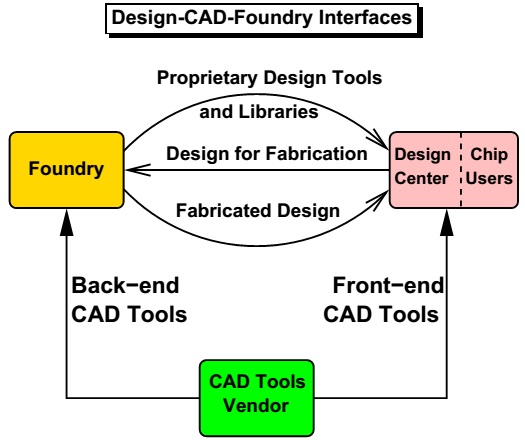
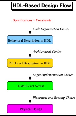
Electronic Design Automation (EDA) or ECAD refers to software tools used for designing complex electronic systems such as printed circuit boards and integrated circuits. EDA tools follow a design flow that enables chip designers to create, simulate, and verify semiconductor chips efficiently.
HDL and VHDL Overview
Hardware Description Languages (HDLs) are formal languages for designing, simulating, and modeling digital circuits. The two most common HDLs are VHDL and Verilog. VHDL (VHSIC Hardware Description Language) is widely used in academics, while Verilog is preferred in industry. VHDL became an IEEE standard (1076) in 1987.
VHDL allows modeling digital systems at multiple levels: algorithmic, register-transfer, gate-level, and structural. It can describe both external interfaces and internal behavior hierarchically, including timing specifications.
VHDL Constructs
- Sequential language
- Concurrent language
- Netlist description
- Timing specifications
- Waveform generation
VHDL hardware abstraction has two views:
- External (interface of the entity)
- Internal (architecture and logic)
VHDL uses Design Units to describe entities:
- Entity declaration
- Architecture body
- Configuration declaration
- Package declaration
- Package body
Entity and Architecture
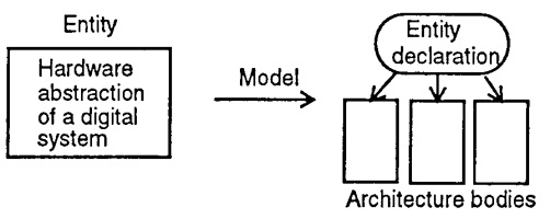
An entity describes the external interface (inputs, outputs) of a module. Each entity has at least one architecture body, which defines internal behavior using structural, behavioral, dataflow, or mixed styles.
Example Entity:
ENTITY mux IS
PORT (a, b, c, d: IN BIT;
      s0, s1: IN BIT;
      x: OUT BIT);
END mux;
Example Architecture (Dataflow style):
ARCHITECTURE dataflow OF mux IS
SIGNAL select: INTEGER;
BEGIN
select <= 0 WHEN s0 = '0' AND s1 = '0' ELSE
         1 WHEN s0 = '1' AND s1 = '0' ELSE
         2 WHEN s0 = '0' AND s1 = '1' ELSE
         3;
x <= a AFTER 0.5 NS WHEN select = 0 ELSE
     b AFTER 0.5 NS WHEN select = 1 ELSE
     c AFTER 0.5 NS WHEN select = 2 ELSE
     a AFTER 0.5 NS;
END dataflow;
Other VHDL Constructs
- Configuration Declaration: Binds architecture to entity and components.
- Package Declaration: Groups reusable types, constants, and procedures.
- Package Body: Implements subprograms declared in the package.
EDA Design Flow
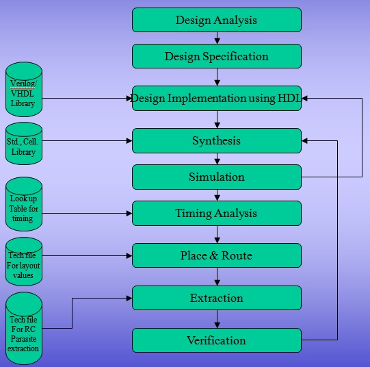
The typical EDA design flow includes the following stages:
- Synthesis: Converts HDL to gate-level netlist using standard cell libraries.
- Simulation: Verifies the netlist’s functional correctness.
- Timing Analysis: Accounts for signal propagation delays.
- Place & Route: Implements the circuit at the semiconductor layout level.
- Extraction: Calculates parasitic capacitances and resistances.
- Verification: Checks functionality and performance of the final design.
Using Xilinx ISE 9.2i
Xilinx ISE allows creating VHDL programs, simulating them, and viewing RTL schematics. After simulation, testbench waveforms (TBW) and input/output signals are displayed, providing practical insights into HDL design.
Conclusion
Familiarity with EDA tools such as Xilinx ISE and VHDL enables designers to model, simulate, and verify digital circuits efficiently. Understanding synthesis, simulation, and timing analysis ensures robust VLSI design implementation.